TommyPROM32 PCB
TommyPROM32
The TommyPROM32 PCB supports 32-pin and smaller EEPROM and Flash chips. The board can be easily configured for many 32, 28, or 24 pin chips or used in its default setup for SST39SF devices. The board has a set of headers that allow any of the signals to the target chip to be re-routed.
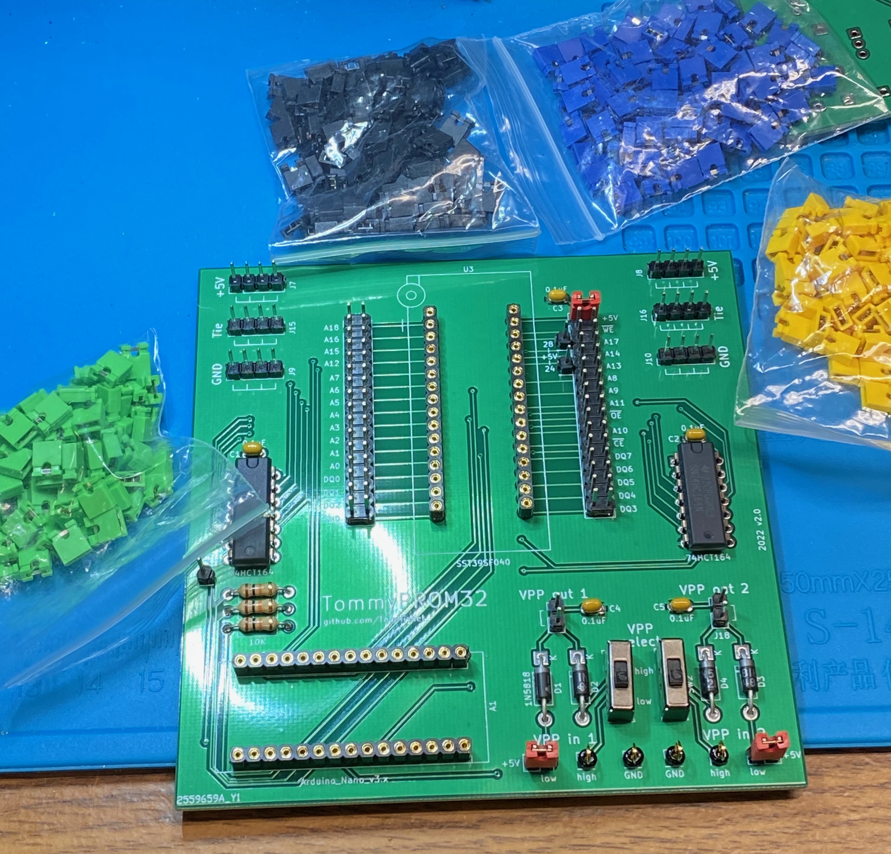
The default configuration and labels, with just jumper shunts (jumper caps) installed, is wired for the SST39SF0x0 chips.

Many other chips, particularly if they follow JEDEC standards, can be supported by removing shunts and adding just a few jumper wires.
If the board is only being used with 5V chips or used to read (but not program) other chips, then the Vpp switches, diodes, and other components on the lower right side of the board do not need to be installed.
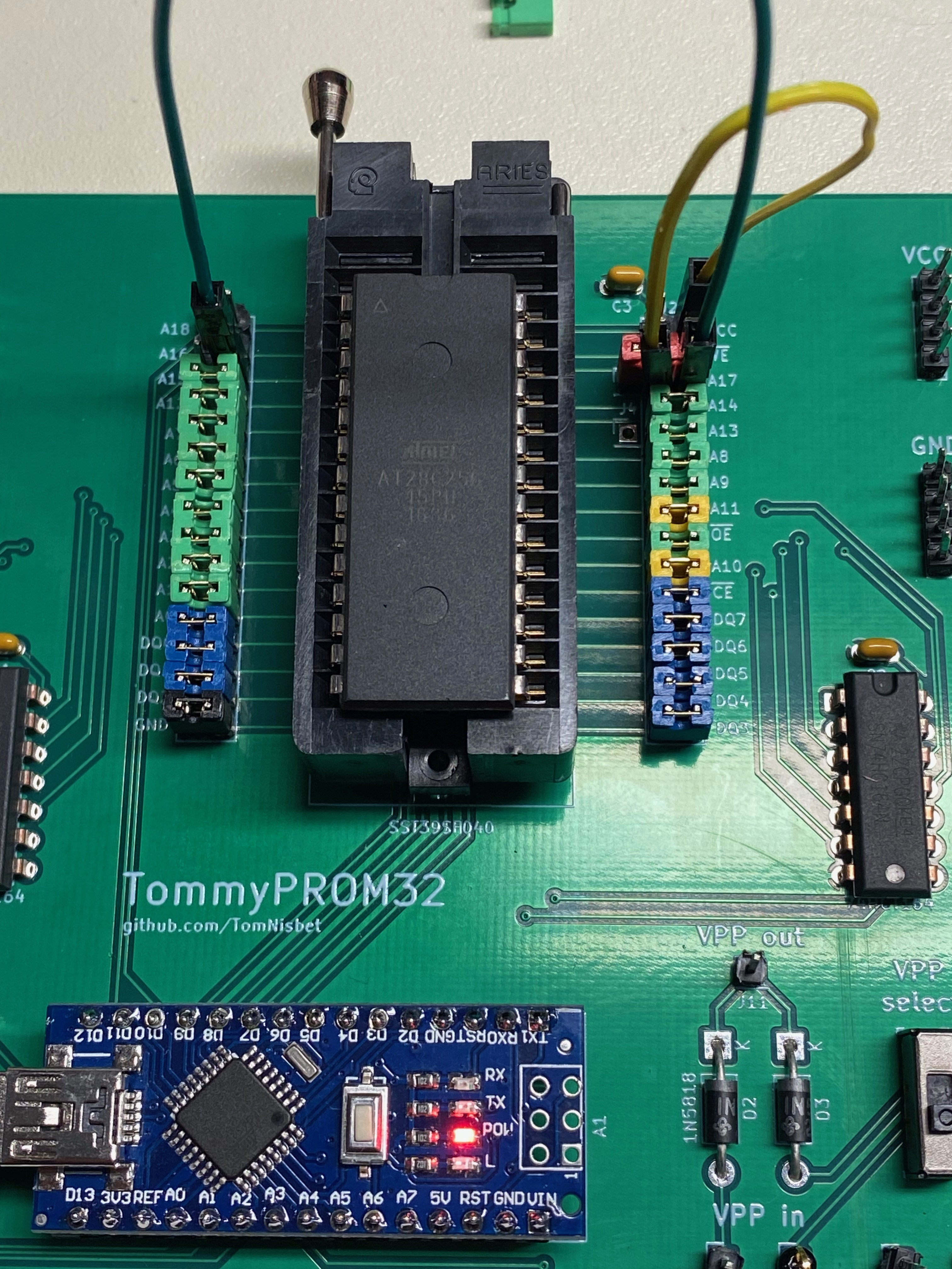
There are power pins in place to support 28-pin and 24-pin chips with a shunt to the correct VCC pin. The photo below shows the 28C256 with a power jumper on pin 28, the WE signal moved down to pin 27, and the A14 signal moved from pin 27 to pin 1.
Vpp Power Selection Examples
Two power inputs and switches are provided to support older flash and EEPROM chips that need higher programming voltages. Many of these chips just need a higher voltage, like 12V, applied to the VPP pin continuously during the programing and verification cycle. In normal operation, the 5V VCC signal is applied to the VPP pin. The board has VPP inputs for two voltages. Applying 12V to VPP In High and 5V to VPP In Low lets the VPP output be switched between these two voltages using a manual slide switch for programming.
Note that some of the photos below show the initial version of the TommyPROM32 board that only contained a single switchable voltage. The version 2.0 boards added a second switchable Vpp voltage section with multiple VPP Output pins. The 5V and Vpp in low pins are now adjacent so that a wire is not needed for the common case where Vpp low is set to 5V. There are also some general-purpose 5v, GND, and interconnect pins.
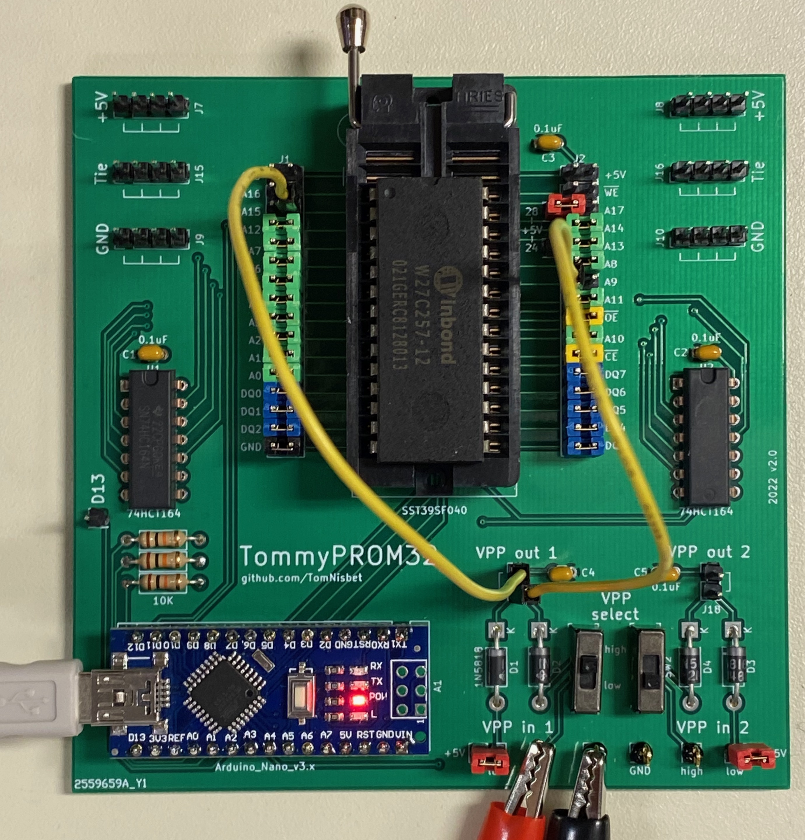
W27C257
The photo below shows the W27C257 set up for programming. The VPP in Low signal is connected to VCC and the VPP in High signal is using 12V from an external power supply. The VPP Out signal is connected to the chip’s VPP on pin 1. The chip is in programming mode when the slide switch is set to the High position and is in read mode when in the Low position.
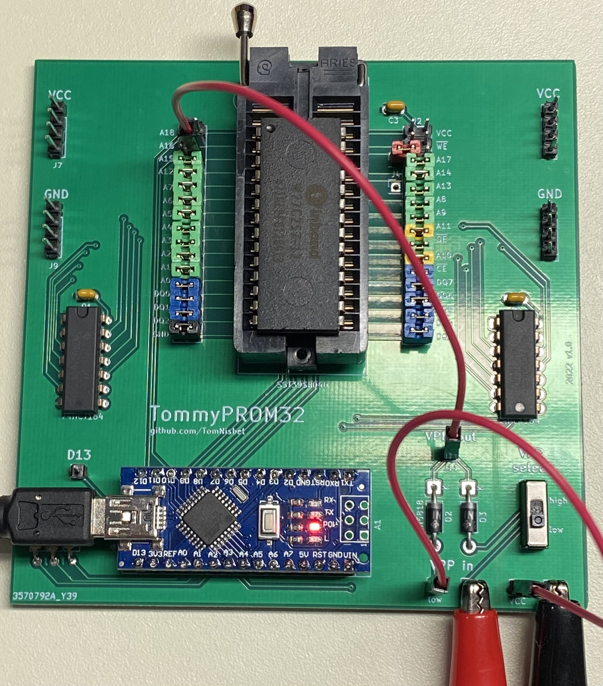
To erase the W27C257 chip, the external power supply is providing 14V and the VPP Out is connected to the chip’s VPP and A9 pins.
Note the the top picture showed the version 1.0 board and a jumper wire was needed to connect +5V to the Vpp in low pin. The newer board, shown below, has a jumper cap to make this connection, so no additional wire is needed.
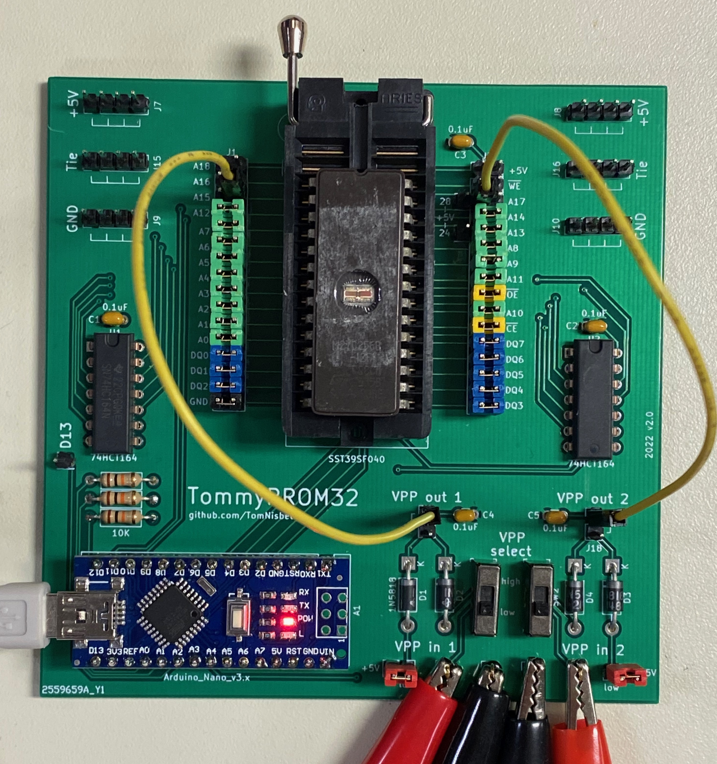
M27C256
The M27C256 chip needs two voltages for programming. The external power supply is providing 12.75V to VPP Out 1 for the the chip’s Vpp pin. The power supply is also providing 6.25V to VPP Out 2 for the chips Vcc pin. Note the the chip’s Vcc is no longer connected to the system +5V. The two VPP Select switches should be in the low position for normal read operation and in the high position for programming.
High Voltage Pulses
For chips that require a high voltage Vpp pulse during programming, some external switching circuitry will be needed to allow the Arduino to control the VPP voltage. There is a header connected to the unused D13 pin that can support this. See the Intel 8755 version of the hardware for an example of voltage switching by TommyPROM.
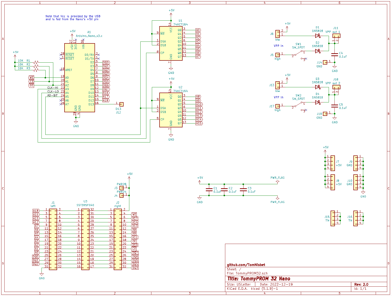
Schematics and Gerbers
The TomyPROM32 KiCad design files are in the project repo.