DXY Adder and Registers
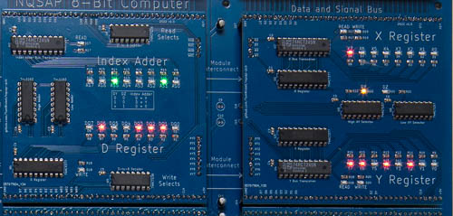
The XY registers and Index Adder are a set of three registers plus a dedicated adder to implement two user-accessible registers and a set of new addressing modes. The X and Y registers are general-purpose registers that are also used as index registers. The D register is a temporary register and adder that is only accessible at the microcode level.
With this hardware, NQSAP is able to use a set of addressing modes similar to those found on a 6502. The only difference is that the NQSAP does not have a sixteen-bit bus, so all of the absolute address modes are the same as the zero-page modes of the 6502. The address modes available are:
- implicit
- accumulator
- immediate
- relative
- absolute
- absolute + X
- absolute + Y
- indirect
- indexed indirect (with X)
- indirect indexed (with Y)
With adder hardware dedicated to addressing modes, ALU instructions that access memory can be implemented in fewer cycles. Without the adder, the instruction AND $40,X would need to use the ALU to calculate $40+X and then would need the ALU again to do the AND operation. This could be done in ten cycles and would need temporary storage to save the accumulator while doing the address calculation. With the DXY register, the instruction can be implemented in only seven microinstructions, including the two for the opcode fetch.
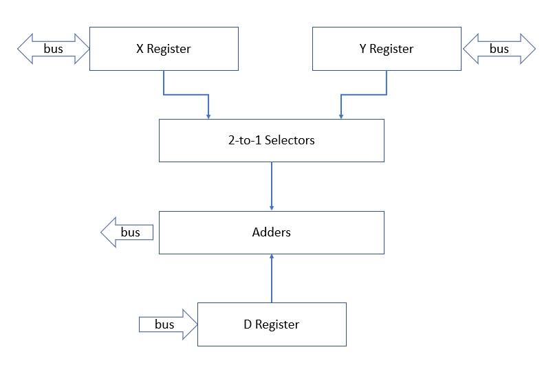
The D register can be added to either the X or Y register to produce a sum that can be read onto the bus. The diagram below shows how the registers are connected.
The 2-to-one selectors allow either X or Y to be selected as a source for the adder. The selectors also have an enable line that presents zero at all of the outputs. By wiring the select and enable lines to the microcode ROMs, the functions D+X, D+Y, or D+0 can be selected.
Hardware
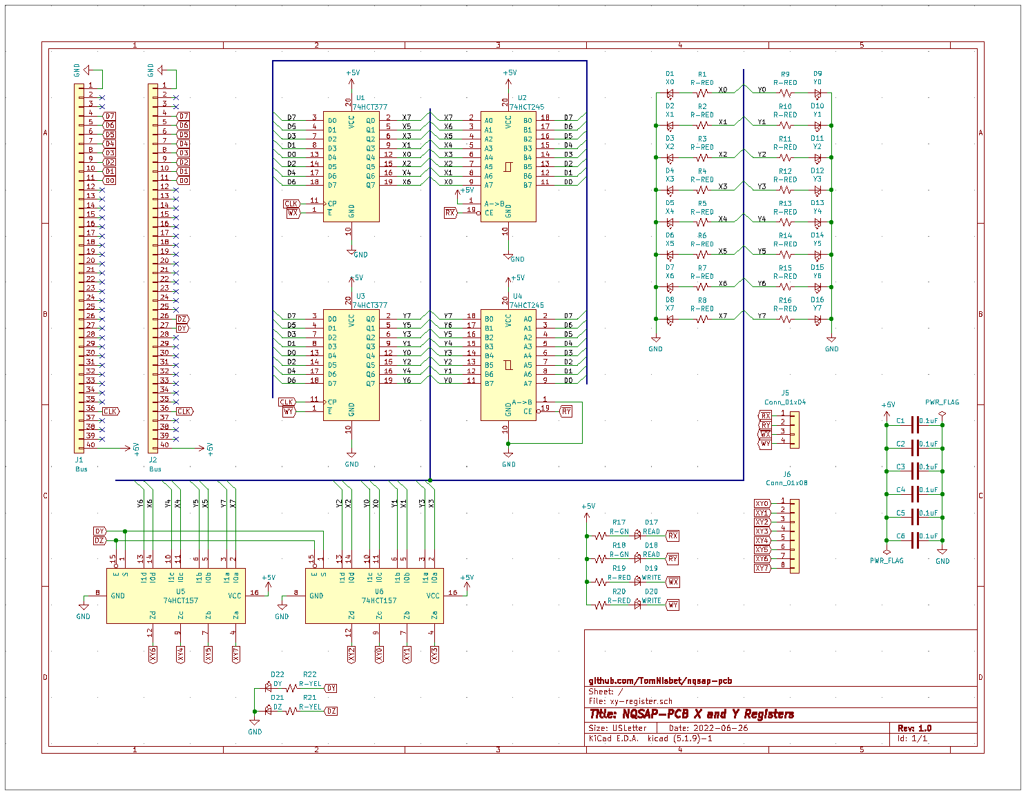
The Index Adder and XY Registers are spread over two module boards, mostly due to the space needed for all of the LEDs. The X and Y registers are each implemented using a 74HCT377 8-bit register and a 74HCT245 8-bit bus transceiver. The X and Y register outputs are connected to the A and B inputs of a pair of 74HCT157 quad 2-to-1 selectors. The selector outputs provide the XY0..7 outputs on the module interconnect bus for the Index Adder module.
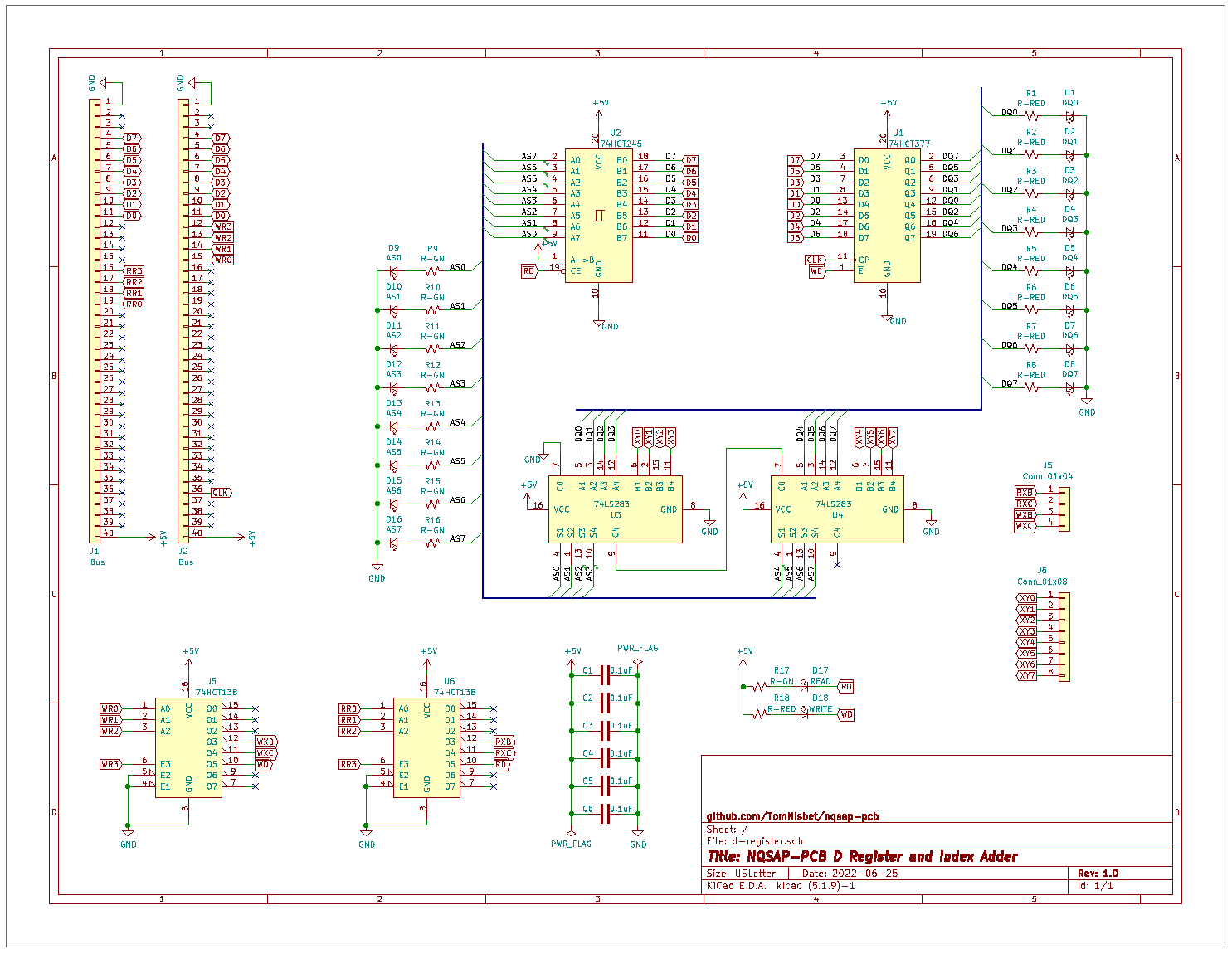
The D register on the Index Adder module also uses the 74HCT377 register. The board contains a pair of 74HCT283 4-bit adders and a 74HCT245 bus transceiver. The inputs to the adders are the D register and the XY data output from the XY module. The DY and DZ lines from the microcode (shared with the C0 and C1 lines) are used to select the XY source for the adder as X, Y, or zero. The outputs of the adders are connected to the bus through the 74HCT245. The D register is not connected to the bus, but it can be read through the adders by selecting the D+zero operation with the DZ control line.
The register select hardware for both boards is contained on the Index Adder module. The read and write signals for X and Y are passed through the module interconnect headers.
Bill of Materials
- 74HCT138 3-to-8 selector(3)
- 74HCT157 quad 2-to-1 selector (2)
- 74HCT283 4-bit adder (2)
- 74HCT245 8-bit bus transceiver (3)
- 74HCT377 8-bit register (3)


