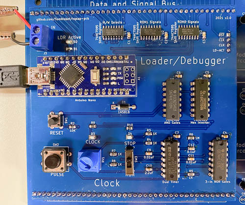
Loader / Debugger
Version 2.0 of the Loader module adds the system clock and master reset circuits to the board. There was space on the board and it makes sense to co-locate these functions to reduce the number of signals that need to be on the control bus. The clock module page has the schematics and circuit description for the clock functionality.
The program memory loader uses an Arduino Nano in place of manual-entry DIP switches on the SAP-1. The Loader/Debugger has eight of the Arduino I/O lines connected directly to the NQSAP host bus for read and write access. It can drive all of the microcode control lines plus the CLK and RST lines.
Beyond the ability to simply load programs into memory, the Loader can read and write all of the NQSAP registers and drive any other control signals. This gives the Loader the capability to perform a comprehensive system verification. This system test is helpful for verifying the operation of new modules.
The Loader writes a default program to the NQSAP memory at power up, allowing unattended operation. If a USB connection is established, the Loader provides a ROM monitor-like command line interface to interact with the NQSAP hardware. The following features are available via the USB interface:
- Memory
- Load memory from a set of programs or patterns that are hard-coded into the Loader
- Dump the contents of memory in hex and ASCII
- Edit memory values
- Fill a section of memory with a value
- Load or save memory to a file using the XMODEM protocol
- Registers
- Read and print the value from a register
- Write a value to a register
- Transfer the value from one register to another
- Diagnostics
- Test all microcode control lines with a walking LED pattern
- Test all registers with a pattern that can be visually observed
- Test all read/write registers by reading back the patterns written
- Test memory with a set of patterns including walking bits
- Test the ALU by writing operands and operations and verifying the result
- Test the right-shifted value of the B register as presented on the H register
- Test the calculation of the flag values and the conditional jumps
- Test the increment and decrement operations of the Stack Pointer
Loader Design
The Loader uses three 74HCT595 8-bit shift registers to drive the twenty-four microcode ROM control outputs. The output enable of these registers is tied to the Loader’s ACTIVE signal and the output enable of the microcode ROMs is the inverted ACTIVE signal, ensuring that only one source will be outputting a signal at any time. The Loader uses four Arduino outputs to drive the inputs of the shift registers.
Loader implementation
The loader uses an Arduino Nano clone. Note that the Loader Arduino is designed to be left in the circuit even when not connected to a controlling computer through USB. Upon power up, the loader will activate itself and then load a default program into the NQSAP. So even in standalone mode, the NQSAP will power up into a state where it has code to execute. There is no manual dip switch loader, so there is no way to load memory without the Arduino.
The Arduino is powered from the NQSAP Vcc through a diode so that if the NQSAP is powered off it does not try to draw power from the Arduino’s USB port. The USB port is connected to the host computer with a hub that has individual power switched, allowing the host computer’s power to be disconnected from the NQSAP.
Bill of Materials
This BOM includes the reset and clock circuitry as well as the Loader.
- 74HCT04 hex inverter (1)
- 74HCT08 quad 2-input AND gate (1)
- 74HCT27 triple 3-input NOR gate (1)
- 74HCT595 8-bit shift register (3)
- NE556 dual timer (1)
- Arduino Nano

